Простой индикатор уровня заряда аккумулятора 3,7 В
Где только сейчас не применяются литий-ионные аккумуляторы напряжением 3,7 В. Самодельщики особенно часто используют их везде где только это возможно. Такие батареи всем хороши, но имеют ряд недостатков, одним из которых является то, что если батарею разряжать ниже минимального значения, то срок ее работы сокращается в геометрической прогрессии. И чтобы этого избежать, и всегда контролировать уровень ее заряда, предлагаю собрать наипростейший индикатор на одном транзисторе, который всегда подскажет в каком состоянии находится аккумулятор.
Понадобится:
Сборка индикатора уровня для батареи 3,7 В
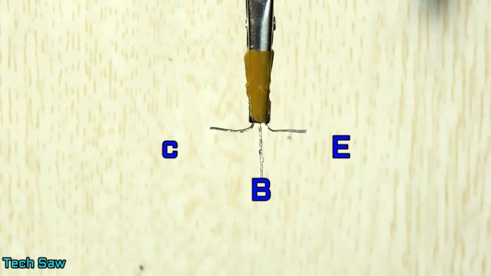
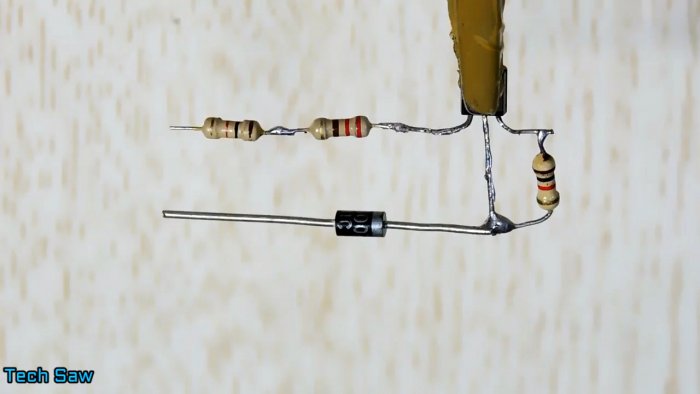
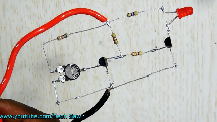
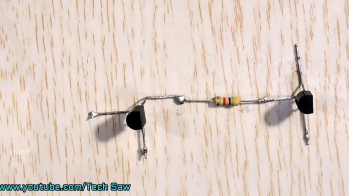
Закрепляем транзистор и отгибаем коллектор и эмиттер в стороны.
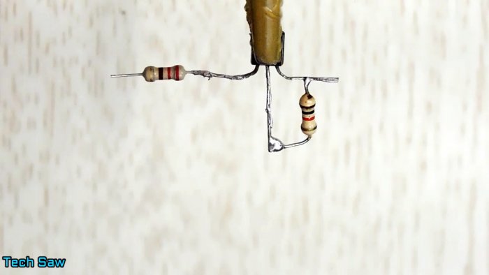
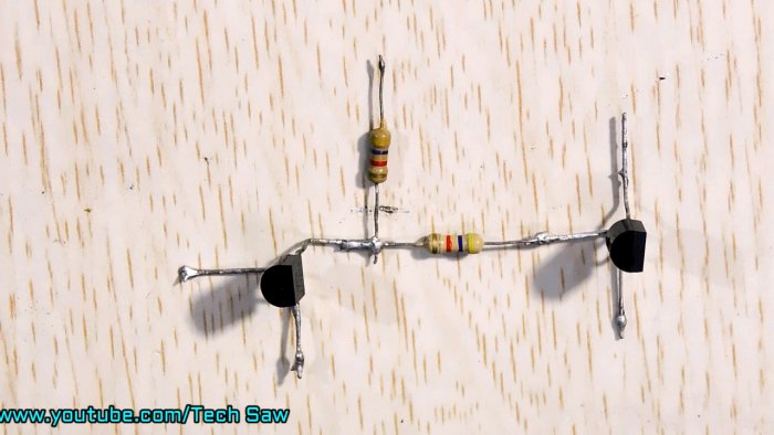
Между базой и эмиттером припаиваем резистор на 220 Ом. А к коллектору резистор 1 кОм.
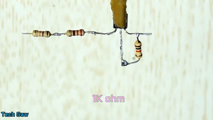
К резистору 1 кОм допаиваем последовательно резистор 220 Ом. Такая цепь нужна для того, чтобы точно подобрать общее сопротивление.
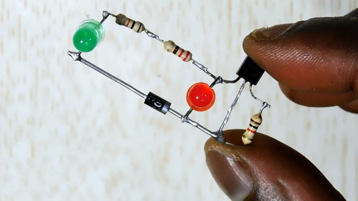
Припаиваем диод.
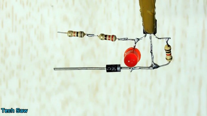
Теперь красный светодиод.
А затем и зеленый.
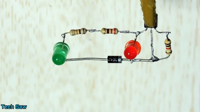
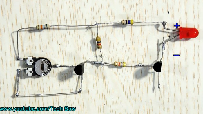
Припаиваем провода питания.
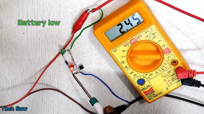
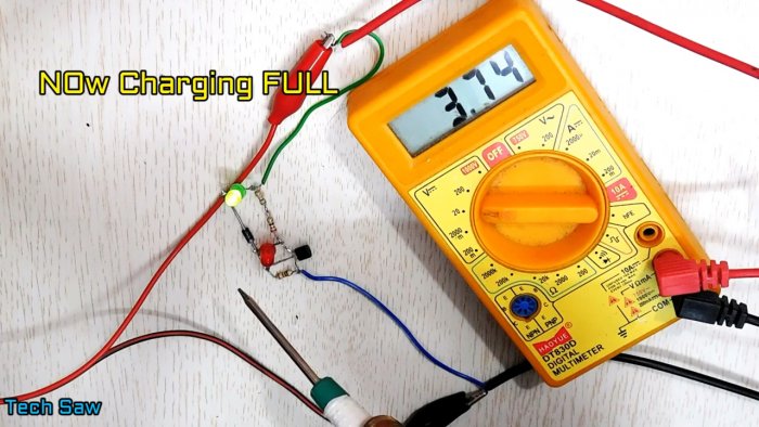
Испытания
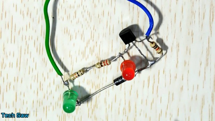
Индикатор имеет пороговое значение в районе 3,3 В. Это значит, что если напряжение ниже этого значения — горит красный, а если выше — зеленый.
Очень удобная «малютка», которую можно встроить куда угодно и всегда знать о состоянии батареи.
Цепочкой из двух последовательно включенных резисторов можно регулировать пороговое значение переключения состояния.
Смотрите видео
Индикатор заряда аккумулятора своими руками

Индикатор заряда аккумулятора своими руками
Индикатор заряда аккумулятора своими руками на двух светодиодах — правильно обслуживаемые аккумуляторы будут работать у вас хорошо и долю. Обслуживание подразумевает, в частности, регулярный контроль напряжения аккумулятора. Изображенная на Рисунке 1 схема подходит для большинства типов аккумуляторов. Она содержит опорный светодиод LED
Это постоянство обеспечивается резистором R1 включенным последовательно со светодиодом. Поэтому, даже если напряжение полностью заряженного аккумулятора упадет до полного разряда, ток через него изменится всего на 10%. Таким образом, можно считать, что интенсивность излучения остается постоянной в диапазоне напряжений аккумулятора, соответствующем переходу от состояния полного заряда до полного разряда.

Световой поток измерительного светодиода LEDVAR меняется в соответствии с изменениями напряжения аккумулятора. Расположив светодиоды поблизости друг от друга, вы получите возможность легко сравнивать яркость их свечения, и, таким образом, определять статус аккумулятора. Используйте светодиоды с диффузно-рассеивающей линзой, поскольку приборы с прозрачной линзой раздражают ваши глаза. Обеспечьте достаточную оптическую изоляцию светодиодов, чтобы свет одного светодиода не попадал на линзу другого.
Работа измерительного светодиода
Измерительный светодиод работает при токе, меняющемся от 10 мА при полностью заряженном аккумуляторе до значений менее 1 мА при полном разряде. Стабилитрон Dz с последовательным резистором R2 необходимы для того, чтобы ток имел резкую зависимость от напряжения батареи. Сумма напряжения стабилитрона и падения напряжения на светодиоде должна быть чуть меньше, чем самое низкое напряжение аккумулятора. Это напряжение падает на резисторе R

Индикатор заряда аккумулятора своими руками — непосредственно после окончания зарядки аккумулятора напряжение на нем превышает 13 В. Для схемы это безопасно, поскольку ток ограничен значением 10 мА. Если светодиоды горят ярко, быстро отпустите кнопку S11( чтобы не допустить их повреждения (Рисунок 2). Хотя в примере на Рисунке 2 индикатор заряда подключен к 12-вольтовой свинцово-кислотной аккумуляторной батарее, вы без труда можете адаптировать эту схему к другим типам аккумуляторов. Кроме того, вы можете использовать ее для контроля напряжения.
Два зеленых светодиода индуцируют состояние, когда заряд батареи превышает 60%. Набор красных светодиодов показывает, что заряд аккумулятора упал ниже 20%. Светодиоды LEDREFG и LEDREFR подключены через резисторы R1 и R2 сопротивлением 10 кОм. Последовательное измерительными светодиодами, яркость свечения которых изменяется, включены стабилитроны и резисторы R3 и R4 сопротивлением 100 Ом. Диоды D1, D2 и D3 задают требуемое напряжение ограничения. Зависимость яркости свечения светодиодов от состояния аккумулятора показана в Табпице1.

Для расчета интенсивности свечения зеленого измерительного светодиода можно использовать следующее выражение:
VBATT
При токе зеленого светодиода 1 мА
VBATT =103 x 100+0.6+0.6+1.85+9.1=1225B.
Падение напряжения на используемых светодиодах при прямом токе 1 мА равно 1.85 В. Если характеристики светодиодов отличаются, сопротивления резисторов необходимо пересчитать. При этом напряжении светодиоды светятся одинаково, что соответствует заряду аккумулятора на 60%. Описание свинцово-кислотных аккумуляторов можно найти в[1]. Для расчета интенсивности свечения красного измерительного светодиода можно использовать следующее выражение:
VBATT= IR x IOO+VD3+VLEDR+VZD2
При токе зеленого светодиода 1 мА

VBATT =10-3 x 100 +0.6 + 1.85 + 9.1 =11.65 В.
Поскольку при таком напряжении оба красных светодиода светятся одинаково, это означает, что аккумулятор заряжен на 20%. Светодиод LEDVARGvarg не горит. Рисунок 3 показывает, что оба измерительных светодиода светятся ярче опорных, сообщая о том, что аккумулятор заряжен на 100%
ИНДИКАТОР НАПРЯЖЕНИЯ БАТАРЕИ НА 2 LED
После зарядки напряжение аккумулятора составляет максимальное значение, после чего оно медленно падает по мере разрядки. Предельное напряжение, ниже которого батареи не должны разряжаться, очень важно не пропустить, чтоб не испортить сам АКБ. Значит нужен индикатор, который бы указывал состояние заряда батарей и момент, когда их требуется срочно зарядить. Предлагаем собрать простой индикатор напряжения, который в отличии от схем на ОУ выполнен всего на одном транзисторе.
Схема, плата и детали индикатора

Номиналы деталей предназначены под АКБ 24 В:
- R1 — 30k
- R2 — 5k
- P — 10k миниатюрный потенциометр,
- T — транзистор, например BC108B,
- D1 — красный светодиод,
- D — двойной красно-зеленый светодиод.
Сам индикатор представляет собой двойной светодиод с красным и зеленым цветом. Когда аккумуляторные батареи заряжены, светодиод горит только зеленым. Когда он разряжается, при определенном напряжении начинает светиться красный кристалл диода, а зеленый медленно гаснет. Поскольку в определенном диапазоне напряжений оба диода светятся, в результате смешивания света зеленый цвет превращается в желтый, затем в оранжевый, и наконец, когда зеленый светодиод полностью выключается, включается яркий красный цвет. Это уже предельное напряжение и сигнал для того, чтобы перезарядить батареи.
Нижнее напряжение устанавливается с помощью потенциометра P. С другой стороны, диапазон в котором светятся оба LED, будет зависеть от транзистора T, то есть его коэффициента усиления. Когда транзистор имеет низкий коэффициент, оба светодиода загораются практически во всем диапазоне полезных напряжений — это не очень хорошо.
Когда транзистор имеет высокий коэффициент усиления, диапазон общего освещения очень мал и можно установить предельное напряжение довольно точно. Но лучшее решение — когда этот диапазон включает напряжение 2-3 В, тогда светодиод сначала светится желтым, а затем оранжевым светом, что указывает на приближение к граничному напряжению. Этот диапазон обеспечивается транзисторами с коэффициентом усиления 250-300.
Большинство мультиметров, даже дешевых, имеют гнездо для измерения коэффициента усиления транзисторов hfE, поэтому его значение можно будет легко проверить перед сборкой.
Светодиод D1 (красный) не показывает напряжение (хотя и светится), он используется только для задавания соответствующей разности напряжений между зеленым и красным светодиодом (D). Для калибровки индикатора потребуется регулируемый источник питания.
Форум
Обсудить статью ИНДИКАТОР НАПРЯЖЕНИЯ БАТАРЕИ НА 2 LED
Очень удивительно, что во многих автомобилях, пусть даже донехочу напичканной всякой электроникой отсутствует банальный индикатор заряда АКБ. Как определить уровень заряда аккумулятора особенно зимой, когда аккумуляторы особо уязвимы?
Для решения данной проблемы я и смастерил индикатор, схема и сборка которой не займет много времени и особых профессиональных навыков, но базовые умения должны присутствовать. Еще одним плюсом сборки – маленькая себестоимость по отношению к дешевым китайским аналогам, качество которых оставляет желать лучшего.
Схема.

В схеме присутствуют светодиоды, цвета которых и будут обозначать степень зарядки – Красный – от 6-ти до 11-ти вольт; Синий – от 11-ти до 13-ти вольт; Зеленый от 13 вольт. Советую также ознакомиться со статьей “Как определить катод и анод у светодиода“
Запитывать схему рекомендуется от замка зажигания, чтобы индикатор не работал постоянно.
Необходимые элементы:
- Резисторы:
- 1 КОм – 2 шт;
- 220 ОМ – 3 шт;
- 2 КОм – 1 шт.
- Транзисторы:
- ВС547 – 1 шт;
- BC557 – 1 шт.
- Светодиоды:
- RGB светодиод – 3 шт.(можно любые светодиоды)
- Стабилитроны:
- 9.1 v – 1 шт; (9v1)
- 10 v – 1 шт.

Проверяем светодиод тестером на работоспособность, определяем выводы.

Далее примеряем элементы к плате и вырезаем кусок, необходимой величины.

Далее необходимо приклеить светодиод к плате и начать монтаж деталей. Светодиоды рекомендуется выводить на проводах, а не припаивать намертво к плате, так как (скорее всего) эти индикаторы вы будете фиксировать где-то в приборной панели вашего авто. А для наглядности сборки они будут установлены прямо на плате.

Транзисторы.


Конечная сборка.

Заключение.
Данная схема тестировалась около получаса (не на авто) прогоном напряжения. Источником тока был обычный блок питания с регулируемым напряжением от ноутбука. Одним единственным сбоем срабатываения было, то что при переходе от красного и от синего цветов индикатор немного тупил, это связано с тем, что падения напряжения было очень резким и тестер не успевал вовремя фиксировать это, а на обычный АКБ – работать сборка будет безотказно.
Также советую ознакомиться с еще одним вариантом изготовления таких индикаторов – Простой высокоточный индикатор разряда АКБ и Простой индикатор разряда АКБ
Удачи на дорогах.
Автор: Скрыльников Валерий. г. Москва.

ОБЯЗАТЕЛЬНО !!!
Приборы, действия и свойства которых вам мало известны, особенно самоделки, подключайте через предохранители.
Индикатор разряда для любого аккумулятора
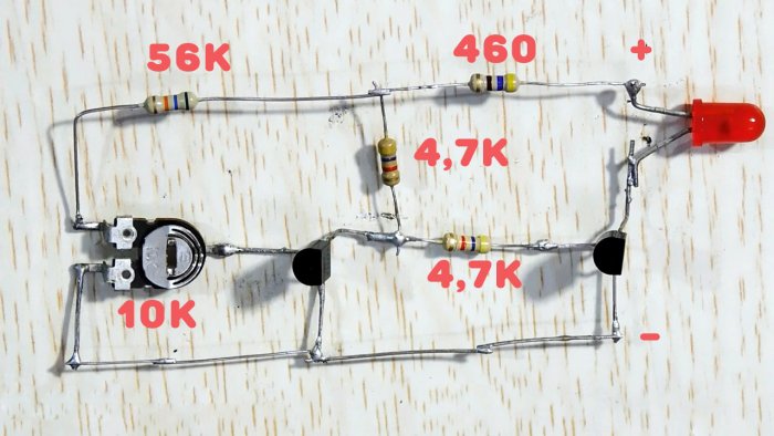
Данная схема характеризуется четким порогом включения при достижении установленного уровня напряжения. Этот индикатор универсален, имеет потенциометр для выставления заданного значения и может работать с любым аккумулятором в диапазоне 3-16 В.
Понадобится
- Два транзистора PN2222, структуры NPN.
- Светодиод 3 В.
- Переменный резистор 10 кОм.
- Два резистора 4,7 кОм.
- По одному резистору 56 кОм и 460 Ом.
Особых требований к деталям нет, все без лишних проблем меняются на аналогичные. В плане резисторов — отклонение от номинала может быть на 10 процентов. Это не страшно, берите близкие по значению.
Изготовление универсального индикатора разряда
Берем транзисторы и разгибаем вывода.

Припаиваем к одному к его базе резистор на 4,7 кОм.
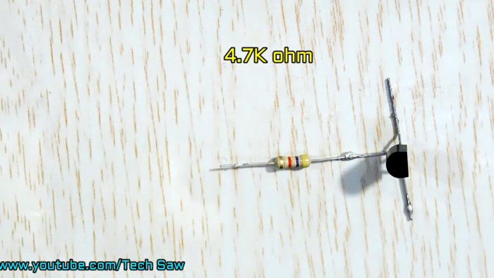
Далее берем второй и коллектором припаиваем к этому же резистору.
Теперь припаиваем еще резистор на 4,7 кОм.
Далее паяем на 56 кОм слева и 460 Ом справа.
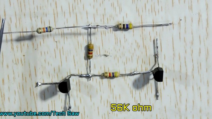
Припаиваем потенциометр.

В дело идет светодиод.
Полная схема со всеми обозначениями.
Как работает схема?
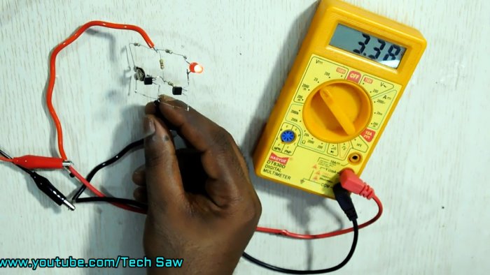
Потенциометром устанавливается уровень срабатывания, это уже решили. На транзисторе слева собран пороговый элемент, на транзисторе справа — ключ для светодиода.
К примеру, выставим уровень срабатывания 3,5 В. Если напряжение на схеме выше, скажем 3,6 В, то первый транзистор открыт, а ключ заперт. Светодиод в данном случае не горит. Индикатор потребляет минимальный ток.
Если напряжение упало ниже порогового значения, и составляет, скажем 3,48 В, то первый транзистор закрывается и открывается ключ. В результате мы видим свечение светодиода, показывающее условно, что аккумулятор разряжен.
Также схема отлично работает в диапазоне 12 В.
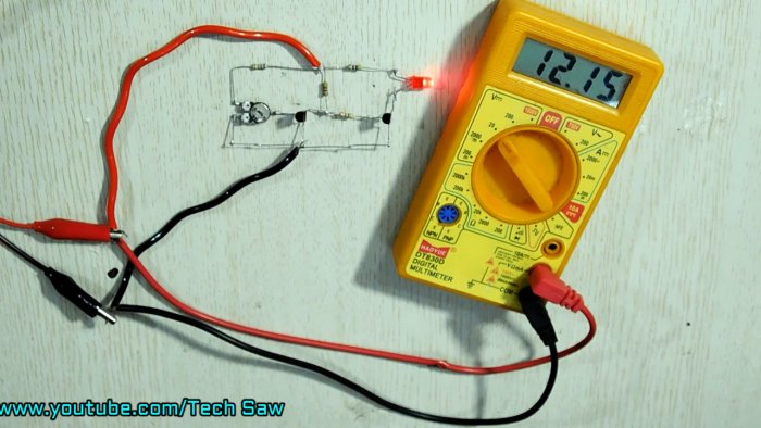
Что дает возможность использовать индикатор для любых аккумуляторов или батарей в промежутке 3-12 В.
Смотрите видео
Индикатор заряда для Li-ion аккумуляторов
Всем привет, мы давно не делали индикаторы разряда автомобильного аккумулятора. Но в этой статье мы будем делать такой, же индикатор только для одной банки LI-ION аккумуляторов с напряжением 3,7 вольт. Такие индикаторы конечно можно купить и на рынке, но, а для тех, кто не прочь поработать руками и мозгами, двигаемся дальше.


Данная схема мало чем отличается от стандартных индикаторов заряда для автомобильных аккумуляторов, но некоторые отличия все же есть. Схема этого индикатора построена на базе компаратора LM-339.

Микросхема LM339 содержит четыре отдельных компаратора, каждый из них имеет два входа и один выход.


Если меняется напряжение на одном входе, это моментально приводит к изменению состояния выхода компаратора.  В случаем микросхемы LM 339 на выходе может быть либо вообще ничего, либо масса или минус питания. Такой компаратор называется с открытым коллектором, поэтому светодиоды подключены катодами к компаратору.

На некоторых входах компаратора нужно формировать стабильное или опорное напряжение.


Как правило, для этих целей используется стабилитрон, но дело в том, что мы собираемся контролировать напряжение на низковольтном источнике. Сам стабилитрон также должен быть низковольтным. Точнее говоря напряжение стабилизации стабилитрона должно быть меньше чем напряжение максимально разряженного аккумулятора.

В случае же обычных LI-ION аккумуляторов это около 3-х вольт. Исходя из выше написанного, для сборки необходимо найти стабилитрон с напряжением стабилизации на 2,5 и меньше вольт. (в нашем случае был использован стабилитрон на 3,3 вольт ).

Решение такое – использовать светодиод в качестве источника опорного напряжения. Для красных, желтых и зеленых светодиодов минимальное напряжение свечения – в пределах 2 вольт, только светодиод уже подключается в прямом направлении в отличие от стабилитрона. Резистивные делители на входах компаратора пришлось пересчитать под литиевый аккумулятор. Была сделана новая плата, рассчитанная для работы с банками 3,7 вольт. Еще один момент на плате есть две перемычки, обозначенные желтыми линиями.


Диод VD1 защищает микросхему, в случае если вы перепутаете полярность подключения к аккумулятору.

Как нам известно, напряжение полностью заряженного литий-ионного аккумулятора должно быть в районе 4,2 вольт, поэтому делители подобраны в очень узком диапазоне, при том использованы резисторы с погрешностью всего в 1 %., что гарантирует высокоточную работу индикатора. На плате имеем 4 индикаторных светодиода (цвета могут быть разными).

Для проверки работоспособности индикатора, его необходимо вначале подключить к лабораторному источнику питания, с выставленным напряжением 4,2 вольт имитируя полностью заряженный литий ионный аккумулятор.


Как видно, все светодиоды горят. Далее постепенно снижаем напряжение, имитируя разряд аккумулятора, и сразу видим поочередное потухание светодиодов при определенных напряжениях. Все работает.
Такой индикатор можно пристроить под какую-нибудь самоделку или использовать в качестве пробника для литиевых банок.
Вот и все, Не забывайте поделиться с друзьями и посвить лайк тем самым, вы поддержите проект.
Индикаторы разряда автомобильного аккумулятора ВАРИАНТ – 1 , ВАРИАНТ – 2 , ВАРИАНТ – 3.
Прикрепленные файлы – СКАЧАТЬ
Автор: Ака Касьян
Дешевый индикатор заряда аккумулятора.
Небольшой обзор с тестами уровня напряжения и показаниями на индикаторе.Началось все честно говоря давно, я только купил TS100, но не дошел до PD повербанков, стояла задача питать паяльник от аккумуляторов, при этом была важна компактность, удобность зарядки и индикатор уровня заряда прямо на банке. Кроме того, напряжение до 15в, дабы питать видео свет.
решение напросилось простое -3S1p аккумуляторная сборка из 18650 для ноутбука. Конечно сразу стоит сказать что емкость такой сборки не супер как и ток, но отборные аккумы на 2000mAh, и небольшое потребление паяльника при 12в, развеяли все сомнения, надо собирать.
BMS был выбран в виде зеленой платы, ссылка.
Корпус по началу сделан и коретки на 3 аккумулятора, но потом были напечатаны ячейки, а аккумуляторы спаяны. Заряжалось все через плату понижающего преобразователя, с контролем тока.
Оставались 2 части пазла, корпус и индикатор уровня заряда. О последнем и поговорим.
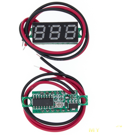
Для начала хотел купит обычный народный мини вольтметр,
https://aliexpress.ru/item/32672092022.html
Стоит дешево, показывает напряжение, а после калибровки, даже с неплохой точностью.
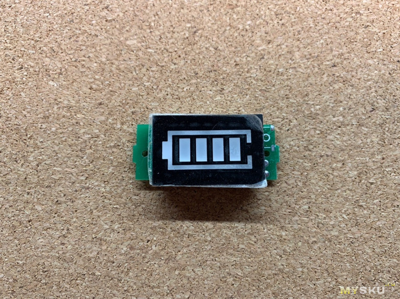
Но пока листал али, нашел интересный вариант. Без цифр а сразу с индикатором аккумулятора и его заполнения, как на телефоне. Точность не супер за счет всего четырех состояний экрана, но почему нет?..
Характеристик никаких не заявлено, лишь фото где видно что заряд отображается четырьмя диодами, а так же выбор индикатора для 1S 2S 3S 4S аккумулятора.
Заказ был обработан за 4 дня, и отправлен почтой «Cainiao Super Economy» при том с треком который так никогда и не заработал. Посылка шла доолго, около 70 дней, иногда почта не любит своих пользователей.
Упаковка в виде стандартного желтого пакета + целофановый пакет в котором само устройство.
Судя по виду, пришло то что заказывал. Сам экран в пленочке. Проводов нет.
Общие размеры — 42х20х9мм.
Плата 42х17х1мм.
Экран отдельно -32х20х6мм.
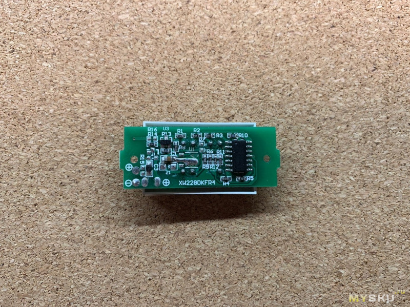
Сзади платы находится вся электроника.
А именно операционный усилитель LM324. Защита от переплюсовки в виде диода, и куча резисторов.
Конкретно за определение уровней заряда отвечают r6 r9 r11 r12.
Так как модуль на низкое напряжение, линейный понижающий стабилизатор не распаян, а на его месте стоит перемычка.
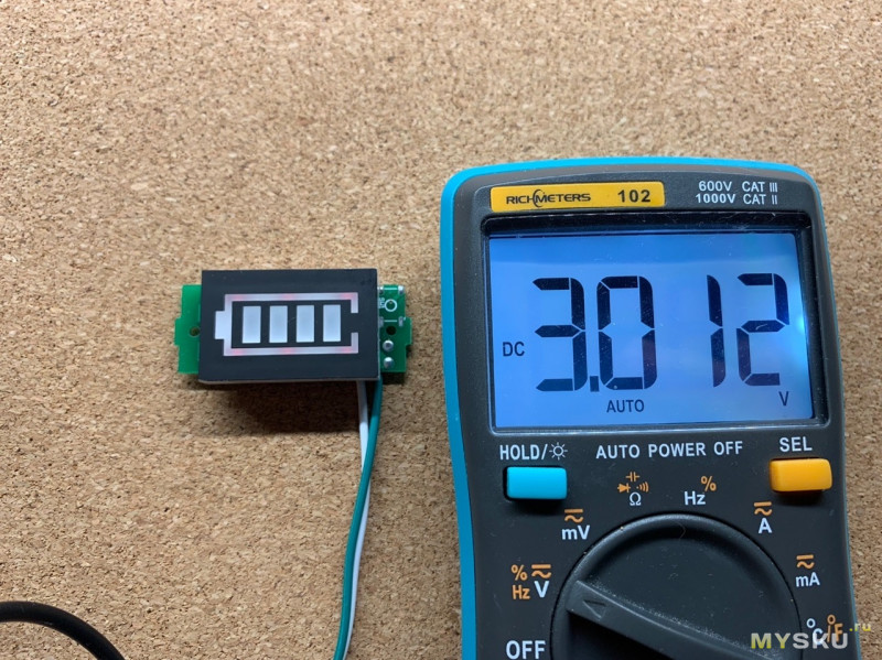
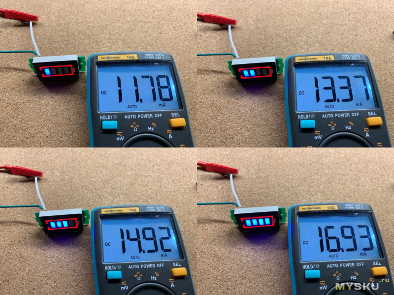
Легкое свечение модуль начинает уже при напряжении 3в
На 10в, силуэт аккумулятора хорошо виден и далее не становится ярче.
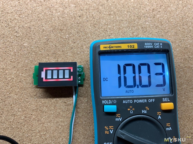
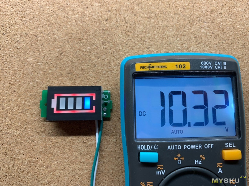
Все что ниже 10.3в для индикатора — 0 делений.
Первое деление появляется при напряжении 10.32в
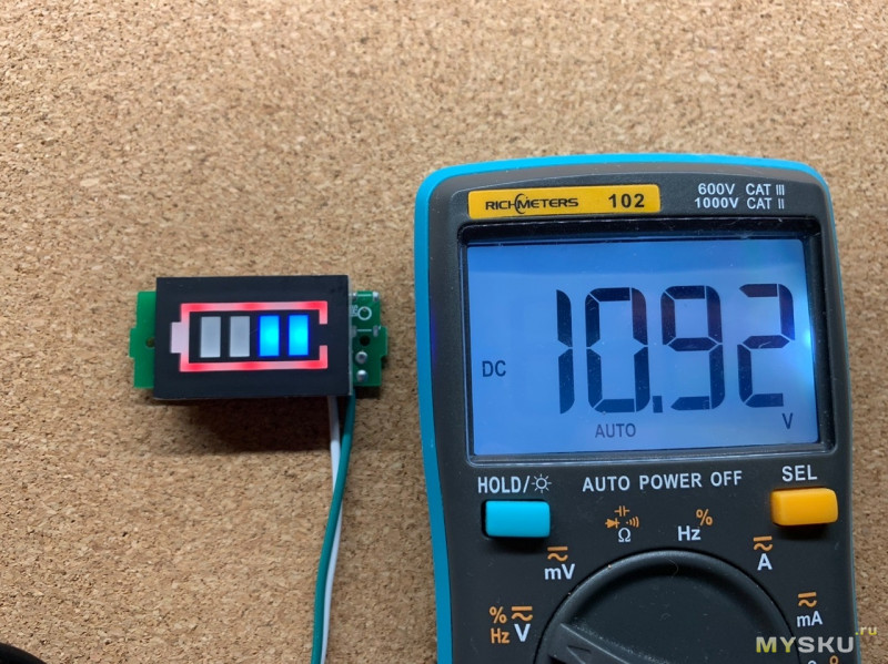
Второе деление появляется при напряжении 10.92в и выше
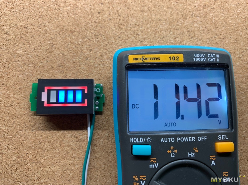
3 деление при напряжении 11.42в
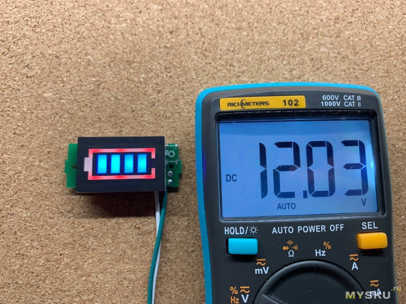
И последнее четвертое деление загорелось после 12.03в
Пример того как загораются деления.
Ток потребления при разных уровнях индикатора.
Теперь немного лирики.
Начнем с нижнего порога в 10.3в. Так как это индикатор для 3S аккумулятора, поделив напряжение на 3 аккума, получаем 3.44в, которые индикатор считает малым уровнем заряда, что вполне нормально.
Верхний порог в 12в тоже приемлем, так как полный заряд 3 банок будет на уровне 12.6в. Как видим, по уровням все в целом неплохо. И при полном разряде, плата защиты BMS — Отключит напряжение на выходе, и не даст разрядить аккумулятор. Но раз у нас есть место на плате и красная окантовка, то почему бы не выключать ее при напряжении ниже уровня например в 8.1в ( 2.7в на каждом аккумуляторе).
Вторым моментом что не понравилось — контакты питания. Их на модуле 4 штуки, все помечены, но те что на торце не работают. Они сделаны для исполнения модуля с кнопкой, и запитывают модуль если кнопка нажата.
В остальном же модуль понравился. Он вполне выполняет свои задачи и пригодится для самоделок, в которых будет наглядно показывать уровень заряда батареи. Но если вам хочется следить за зарядом точнее, то конечно лучше взять вольтметр за ровно ту же цену.
90000 Light-Emitting Diodes (LEDs) — learn.sparkfun.com 90001 Favorited Favorite 52 90002 Introduction 90003 90004 90005 LEDs are all around us: 90006 In our phones, our cars and even our homes. Any time something electronic lights up, there’s a good chance that an LED is behind it. They come in a huge variety of sizes, shapes, and colors, but no matter what they look like they have one thing in common: they’re the bacon of electronics.They’re widely purported to make any project better and they’re often added to unlikely things (to everyone’s delight). 90007 90004 Unlike bacon, however, they’re no good once you’ve cooked them. This guide will help you avoid any accidental LED barbecues! First things first, though. What exactly 90009 is 90010 this LED thing everyone’s talking about? 90007 90004 LEDs (that’s «ell-ee-dees») are a particular type of diode that convert electrical energy into light. In fact, LED stands for «Light Emitting Diode.»(It does what it says on the tin!) And this is reflected in the similarity between the diode and LED schematic symbols: 90007 90004 In short, LEDs are like tiny lightbulbs. However, LEDs require a lot less power to light up by comparison. They’re also more energy efficient, so they do not tend to get hot like conventional lightbulbs do (unless you’re really pumping power into them). This makes them ideal for mobile devices and other low-power applications. Do not count them out of the high-power game, though.High-intensity LEDs have found their way into accent lighting, spotlights and even automotive headlights! 90007 90004 Are you getting the craving yet? The craving to put LEDs on everything? Good, stick with us and we’ll show you how! 90007 90018 Suggested Reading 90019 90004 Here are some other topics that will be discussed in this tutorial. If you are unfamiliar with any of them, please have a look at the respective tutorial before you go any further. 90007 90018 What is a Circuit? 90019 90004 Every electrical project starts with a circuit.Do not know what a circuit is? We’re here to help. 90007 90018 What is Electricity? 90019 90004 We can see electricity in action on our computers, lighting our houses, as lightning strikes in thunderstorms, but what is it? This is not an easy question, but this tutorial will shed some light on it! 90007 90018 Diodes 90019 90004 A diode primer! Diode properties, types of diodes, and diode applications.90007 90018 Electric Power 90019 90004 An overview of electric power, the rate of energy transfer. We’ll talk definition of power, watts, equations, and power ratings. 1.21 gigawatts of tutorial fun! 90007 90018 Polarity 90019 90004 An introduction to polarity in electronic components. Discover what polarity is, which parts have it, and how to identify it. 90007 90018 Suggested Viewing 90019 90004 90045 90046 90007 90002 How to Use Them 90003 90004 So you’ve come to the sensible conclusion that you need to put LEDs on everything.We thought you’d come around. 90007 90004 Let’s go over the rule book: 90007 90018 1) Polarity Matters 90019 90004 In electronics, polarity indicates whether a circuit component is symmetric or not. LEDs, being diodes, will only allow current to flow in one direction. And when there’s no current-flow, there’s no light. Luckily, this also means that you can not break an LED by plugging it in backwards. Rather, it just will not work. 90007 90004 The positive side of the LED is called the 90005 «anode» 90006 and is marked by having a longer «lead,» or leg.The other, negative side of the LED is called the 90005 «cathode.» 90006 Current flows from the anode to the cathode and never the opposite direction. A reversed LED can keep an entire circuit from operating properly by blocking current flow. So do not freak out if adding an LED breaks your circuit. Try flipping it around. 90007 90018 2) Moar Current Equals Moar Light 90019 90004 The brightness of an LED is directly dependent on how much current it draws. That means two things. The first being that super bright LEDs drain batteries more quickly, because the extra brightness comes from the extra power being used.The second is that you can control the brightness of an LED by controlling the amount of current through it. But, setting the mood is not the only reason to cut back your current. 90007 90018 3) There is Such a Thing as Too Much Power 90019 90004 If you connect an LED directly to a current source it will try to dissipate as much power as it’s allowed to draw, and, like the tragic heroes of olde, it will destroy itself. That’s why it’s important to limit the amount of current flowing across the LED.90007 90004 For this, we employ resistors. Resistors limit the flow of electrons in the circuit and protect the LED from trying to draw too much current. Do not worry, it only takes a little basic math to determine the best resistor value to use. You can find out all about it in the example applications of our resistor tutorial! 90007 90018 Resistors 90019 90076 April 1, 2013 90 077 90004 A tutorial on all things resistors. What is a resistor, how do they behave in parallel / series, decoding the resistor color codes, and resistor applications.90007 90004 Do not let all of this math scare you, it’s actually pretty hard to mess things up too badly. In the next section, we’ll go over how to make an LED circuit without getting your calculator. 90007 90002 LEDs Without Math 90003 90004 Before we talk about how to read a datasheet, let’s hook up some LEDs. After all, this is an LED tutorial, not a 90009 reading 90010 tutorial. 90007 90004 It’s also not a math tutorial, so we’ll give you a few rules of thumb for getting LEDs up and running.As you’ve probably put together from the info in the last section, you’ll need a battery, a resistor, and an LED. We’re using a battery as our power source, because they’re easy to find and they can not supply a dangerous amount of current. 90007 90004 The basic template for an LED circuit is pretty simple, just connect your battery, resistor and LED in series. Like this: 90091 90007 90091 90018 330 Ohm Resistor 90019 90004 A good resistor value for most LEDs is 90005 330 Ohms 90006 (orange — orange — brown).You can use the information from the last section to help you determine the exact value you need, but this is LEDs 90009 without 90010 math … So, start by popping a 330 Ohm resistor into the above circuit and see what happens. 90007 90018 Trial and Error 90019 90004 The interesting thing about resistors is that they’ll dissipate extra power as heat, so if you have a resistor that’s getting warm, you probably need to go with a smaller resistance. If your resistor is too small, however, you run the risk of burning out the LED! Given that you have a handful of LEDs and resistors to play with, here’s a flow chart to help you design your LED circuit by trial and error: 90091 90007 90091 90018 Throwies with a Coin Cell Battery 90019 90004 Another way to light up an LED is to just connect it to a coin cell battery! Since the coin cell can not source enough current to damage the LED, you can connect them directly together! Just push a CR2032 coin cell between the leads of the LED.The long leg of the LED should be touching the side of the battery marked with a «+». Now you can wrap some tape around the whole thing, add a magnet, and stick it to stuff! Yay for throwies! 90007 90004 Of course, if you’re not getting great results with the trial and error approach, you can always get out your calculator and math it up. Do not worry, it’s not hard to calculate the best resistor value for your circuit. But before you can figure out the optimal resistor value, you’ll need to find the optimal current for your LED.For that we’ll need to report to the datasheet … 90007 90002 Get the Details 90003 90004 Do not go plugging any strange LEDs into your circuits, that’s just not healthy. Get to know them first. And how better than to read the datasheet. 90007 90004 As an example we’ll peruse the datasheet for our Basic Red 5mm LED. 90007 90018 LED Current 90019 90004 Starting at the top and making our way down, the first thing we encounter is this charming table: 90007 90004 Ah, yes, but what does it all mean? 90007 90004 The first row in the table indicates how much current your LED will be able to handle continuously.In this case, you can give it 20mA or less, and it will shine its brightest at 20mA. The second row tells us what the maximum peak current should be for short bursts. This LED can handle short bumps to 30mA, but you do not want to sustain that current for too long. This datasheet is even helpful enough to suggest a stable current range (in the third row from the top) of 16-18mA. That’s a good target number to help you make the resistor calculations we talked about. 90007 90004 The following few rows are of less importance for the purposes of this tutorial.The reverse voltage is a diode property that you should not have to worry about in most cases. The power dissipation is the amount of power in milliWatts that the LED can use before taking damage. This should work itself out as long as you keep the LED within its suggested voltage and current ratings. 90007 90018 LED Voltage 90019 90004 Let’s see what other kinds of tables they’ve put in here … Ah! 90007 90004 This is a useful little table! The first row tells us what the 90005 forward voltage 90006 drop across the LED will be.Forward voltage is a term that will come up a lot when working with LEDs. This number will help you decide how much voltage your circuit will need to supply to the LED. If you have more than one LED connected to a single power source, these numbers are really important because the forward voltage of all of the LEDs added together can not exceed the supply voltage. We’ll talk about this more in-depth later in the delving deeper section of this tutorial. 90007 90018 LED Wavelength 90019 90004 The second row on this table tells us the wavelength of the light.Wavelength is basically a very precise way of explaining what color the light is. There may be some variation in this number so the table gives us a minimum and a maximum. In this case it’s 620 to 625nm, which is just at the lower red end of the spectrum (620 to 750nm). Again, we’ll go over wavelength in more detail in the delving deeper section. 90007 90018 LED Brightness 90019 90004 The last row (labeled «Luminous Intensity») is a measure of how bright the LED can get. The unit mcd, or 90005 millicandela 90006, is a standard unit for measuring the intensity of a light source.This LED has an maximum intensity of 200 mcd, which means it’s just bright enough to get your attention but not quite flashlight bright. At 200 mcd, this LED would make a good indicator. 90007 90018 Viewing Angle 90019 90004 Next, we’ve got this fan-shaped graph that represents the viewing angle of the LED. Different styles of LEDs will incorporate lenses and reflectors to either concentrate most of the light in one place or spread it as widely as possible. Some LEDs are like floodlights that pump out photons in every direction; Others are so directional that you can not tell they’re on unless you’re looking straight at them.To read the graph, imagine the LED is standing upright underneath it. The «spokes» on the graph represent the viewing angle. The circular lines represent the intensity by percent of maximum intensity. This LED has a pretty tight viewing angle. You can see that looking straight down at the LED is when it’s at its brightest, because at 0 degrees the blue lines intersect with the outermost circle. To get the 50% viewing angle, the angle at which the light is half as intense, follow the 50% circle around the graph until it intersects the blue line, then follow the nearest spoke out to read the angle.For this LED, the 50% viewing angle is about 20 degrees. 90007 90018 Dimensions 90019 90004 Finally, the mechanical drawing. This picture contains all of the measurements you’ll need to actually mount the LED in an enclosure! Notice that, like most LEDs, this one has a small flange at the bottom. That comes in handy when you want to mount it in a panel. Simply drill a hole the perfect size for the body of the LED, and the flange will keep it from falling through! 90007 90004 Now that you know how to decipher the datasheet, let’s see what kind of fancy LEDs you might encounter in the wild… 90007 90002 Types of LEDs 90003 90004 Congratulations, you know the basics! Maybe you’ve even gotten your hands on a few LEDs and started lighting stuff up, that’s awesome! How would you like to step up your blinky game? Let’s talk about makin ‘it fancy outside of your standard LED. 90007 90004 90009 Close Up of Super Bright 5mm LED Close Up 90010 90007 90018 Types of LEDs 90019 90004 Here’s the cast of other characters. 90007 90018 RGB LEDs 90019 90004 RGB (Red-Green-Blue) LEDs are actually three LEDs in one! But that does not mean it can only make three colors.Because red, green, and blue are the additive primary colors, you can control the intensity of each to create every color of the rainbow. Most RGB LEDs have four pins: one for each color, and a common pin. On some, the common pin is the anode, and on others, it’s the cathode. 90007 90004 90009 RGB Common Clear Cathode LED 90010 90007 90018 LEDs w / Integrated Circuits 90019 90076 Cycling 90077 90004 Some LEDs are smarter than others. Take the cycling LED, for example. Inside these LEDs, there’s actually an integrated circuit that allows the LED to blink without any outside controller.Here’s a closeup of the IC (the big, black square chip on the tip of the anvil) controlling the colors. 90007 90004 90009 5mm Slow Cycling LED Close Up 90010 90007 90004 Simply power it up and watch it go! These are great for projects where you want a little bit more action but do not have room for control circuitry. There are even RGB flashing LEDs that cycle through thousands of colors! 90007 90076 Addressable LEDs 90077 90004 Other types of LEDs can be controlled individually.There are different chipsets (WS2812, APA102, UCS1903, to name a few) used to control an individual LED that is chained together. Below is a closeup of a WS2812. The bigger square IC on the right controls the colors individually. 90007 90004 90009 Addressable WS2812 PTH Close Up 90010 90007 90076 Built-In Resistor 90077 90004 What is this magic? An LED with a built-in resistor? That’s right. There are also LEDs that include a small, current limiting resistor. If you look closely at the image below, there is a small, black square IC on the post to limit the current on these types of LEDs.90007 90004 90009 LED with Built-In Resistor Close Up 90010 90007 90004 So plug the LED with built-in resistor to your power source and light it up! We have tested these types of LEDs at 3.3V, 5V, and 9V. 90007 90004 90009 Super Bright Green LED with Built in Resistor Powered 90010 90007 90004 90005 Note: 90006 The datasheet for the LEDs with built-in resistor indicates that the recommended forward voltage is around 5V. Testing one out at 5V, it pulls about 18mA.Stress testing with a 9V battery, it pulls about 30mA. This is probably at the higher end of the input voltage. Using a higher voltage can reduce the life of the LED. At about 16V, the LED blew out under our stress tests. 90007 90018 Surface Mount (SMD) Packages 90019 90004 SMD LEDs are not so much a specific kind of LED but a package type. As electronics get smaller and smaller, manufacturers have figured out how to cram more components in a smaller space. SMD (Surface Mount Device) parts are tiny versions of their standard counterparts.Here’s a closeup of a WS2812B addressable LED packaged into a small 5050 package. 90007 90004 90009 Addressable WS2812B Close Up 90010 90007 90004 SMD LEDs come in several sizes, from fairly large to smaller than a grain of rice! Because they’re so small, and have pads instead of legs, they’re not as easy to work with, but if you’re tight on space, they might be just what the doctor ordered. 90007 90226 90227 90228 90229 90228 90229 90232 90227 90228 90235 WS2812B-5050 Package 90236 90229 90228 90235 APA102-2020 Package 90236 90229 90232 90243 90004 SMD LEDs also make it easier and quicker for pick and place machines to 90005 populate a lot 90006 of LEDs onto PCBs and strips.You would probably not to manually solder all of those components by hand. 90007 90226 90227 90228 90229 90228 90229 90232 90227 90228 90235 Close Up of 8×32 Addressable (WS2812-5050) LED Matrix 90236 90229 90228 90235 5M Addressable (APA102-5050) LED Strip Powered 90236 90229 90232 90243 90018 High Power 90019 90004 High-Power LEDs from manufacturers like Luxeon and CREE, are crazy bright. These are brighter than the super brights! Generally, an LED is considered High-Power if it can dissipate 1 Watt or more of power.These are the fancy LEDs that you find in really nice flashlights. Arrays of them can even be built for spotlights and automobile headlights. Because there’s so much power being pumped through the LED, these often require heatsinks. A heatsink is basically a chunk of heat conducting metal with lots of surface area whose job is to transfer as much waste heat into the surrounding air as possible. There can be some heat dissipation built into the design of some breakout board such as the one shown below.90007 90226 90227 90228 90229 90228 90229 90232 90227 90228 90235 High Power RGB LED 90236 90229 90228 90235 Aluminum Back for some Heat Dissipation 90236 90229 90232 90243 90004 High-Power LEDs can generate so much waste heat that they’ll damage themselves without proper cooling. Do not let the term «waste heat» fool you, though, these devices are still incredibly efficient compared to conventional bulbs. To control, you could use a constant current LED driver.90007 90018 Special LEDs 90019 90004 There are even LEDs that emit light outside of the normal visible spectrum. You probably use infrared LEDs every day, for instance. They’re used in things like TV remotes to send small pieces of information in the form of invisible light! These may look like standard LEDs so it will be hard to distinguish from normal LEDs. 90007 90004 90009 IR LED 90010 90007 90004 On the opposite end of the spectrum you can also get ultraviolet LEDs. Ultraviolet LEDs will make certain materials fluoresce, just like a blacklight! They’re also used for disinfecting surfaces, because many bacteria are sensitive to UV radiation.They may also be used counterfeit detection (bills, credit cards, documents, etc), sun burns, the list goes on. Please wear eye protection when using these LEDs. 90007 90004 90009 UV LED Inspecting a US Bill 90010 90007 90018 More LEDs 90019 90004 With fancy LEDs like these at your disposal, there’s no excuse for leaving anything un-illuminated. However, if your thirst for LED knowledge has not been slaked, then read on, and we’ll get into the nitty-gritty on LEDs, color, and luminous intensity! 90007 90002 Delving Deeper 90003 90004 So you’ve graduated from LEDs 101 and you want more? Oh, do not worry, we’ve got more.Let’s start with the science behind what makes LEDs tick … err … blink. We’ve already mentioned that LEDs are a special kind of diode, but let’s delve a little deeper into exactly what that means: 90007 90004 What we call an LED is really the LED and the packaging together, but the LED itself is actually tiny! It’s a chip of semiconductor material that’s doped with impurities which creates a boundary for charge carriers. When current flows into the semi-conductor, it jumps from one side of this boundary to the other, releasing energy in the process.In most diodes that energy leaves as heat, but in LEDs that energy is dissipated as light! 90007 90004 The wavelength of light, and therefore the color, depends on the type of semiconductor material used to make the diode. That’s because the energy band structure of semiconductors differs between materials, so photons are emitted with differing frequencies. Here’s a table of common LED semiconductors by frequency: 90007 90009 Truncated table of semiconductor materials by color. The full table is available on the Wikipedia entry for «LED» 90010 90004 While the wavelength of the light depends on the band gap of the semiconductor, the intensity depends on the amount of power being pushed through the diode.We talked about luminous intensity a little bit in a previous section, but there’s more to it than just putting a number on how bright something looks. 90007 90004 The unit for measuring luminous intensity is called the candela, although when you’re talking about the intensity of a single LED you’re usually in the millicandela range. The interesting thing about this unit is that it is not really a measure of the amount of light energy, but an actual measure of «brightness». This is achieved by taking the power emitted in a particular direction and weighting that number by the luminosity function of the light.The human eye is more sensitive to some wavelengths of light than others, and the luminosity function is a standardized model that accounts for that sensitivity. 90007 90004 The luminous intesity of LEDs can range from the tens to the tens-of-thousands of millicandela. The power light on your TV is probably about 100 mcd, whereas a good flashlight might be 20,000 mcd. Looking straight into anything brighter than a few thousand millicandela can be painful; do not try it. 90007 90018 Forward Voltage Drop 90019 90004 Oh, I also promised that we’d talk about the concept of Forward Voltage Drop.Remember when we were looking at the datasheet and I mentioned that the Forward Voltage of all of your LEDs added together can not exceed your system voltage? This is because every component in your circuit has to 90009 share 90010 the voltage, and the amount of voltage that every part uses together will always equal the amount that’s available. This is called Kirchhoff’s Voltage Law. So if you have a 5V power supply and each of your LEDs have a forward voltage drop of 2.4V then you can not power more than two at a time.90007 90004 Kirchhoff’s Laws also come in handy when you want to approximate the voltage across a given part based on the Forward Voltage of other parts. For instance, in the example I just gave there’s a 5V supply and 2 LEDs with a 2.4V Forward Voltage Drop each. Of course we would want to include a current limiting resistor, right? How would you find out the voltage across that resistor? It’s easy: 90007 90332 90004 5 (System Voltage) = 2.4 (LED 1) + 2.4 (LED 2) + Resistor 90007 90004 5 = 4.8 + Resistor 90007 90004 Resistor = 5 — 4.8 90007 90004 Resistor = 0.2 90007 90341 90004 So there is .2V across the resistor! This is a simplified example and it is not always this easy, but hopefully this gives you an idea of why Forward Voltage Drop is important. Using the voltage number you derive from Kirchhoff’s Laws you can also do things like determine the current across a component using Ohm’s Law. In short, 90005 you want your system voltage equal to the expected forward voltage of your combined circuit components.90006 90007 90018 Calculating Current Limiting Resistors 90019 90004 If you need to calculate the exact current limiting resistor value in series with an LED, check out one of the example applications in the resistors tutorial for more information. 90007 90002 Resources and Going Further 90003 90004 You’ve made it! You know, like, almost everything … about LEDs. Now go forth and put LEDs on whatever you please! And now … a dramatic reenactment of an LED without a current limiting resistor being over powered and burning itself out: 90007 90004 Yeah… it’s not spectacular. 90007 90004 If you’d like to learn more about some LED related topics, visit these other tutorials: 90007 90018 Light 90019 90004 Light is a useful tool for the electrical engineer. Understanding how light relates to electronics is a fundamental skill for many projects. 90007 90018 IR Communication 90019 90004 This tutorial explains how common infrared (IR) communication works, as well as shows you how to set up a simple IR transmitter and receiver with an Arduino.90007 90018 How LEDs are Made 90019 90004 We take a tour of a LED manufacturer and learn how PTH 5mm LEDs are made for SparkFun. 90007 90018 Motion Controlled Wearable LED Dance Harness 90019 90004 Control LEDs based on your movement using an accelerometer! Make your LEDs breathe by fading in and out when laying on the floor, turn off the LEDs when moving to your side, or make the LEDs blink in a headstand! 90007 90004 90007 90002 Interested in learning more about LEDs? 90003 90004 See our 90005 LED 90006 page for everything you need to know to start using these components in your project.90007 90004 Take me there! 90007 90004 90007 90004 Or check out some of these related blog posts: 90007 90004 90007 .90000 How to make Batteries more Reliable and Longer Lasting — Battery University 90001 90002 Knowing the health of a battery is important, but no quick method exists to test them with certainty. State-of-health (SoH) can not be measured per se, only estimated to various degrees of accuracies based on available symptoms. A battery behaves much like a living organism that is swayed by conditions such as state-of-charge (SoC), charge and discharge events, rest periods, environmental conditions and aging.A battery with low charge behaves similarly to a pack that exhibits capacity loss and these two symptoms become a blur. Battery test methods must look beyond mood swings and capture characteristics that only relate to SoH. 90003 90002 90005 The leading health indicator of a battery is capacity; a unit that represents the ability to store energy. A new battery delivers (should deliver) 100 percent of the rated Ah capacity. Lead acid starts at about 85 percent and the capacity will increase with use before the long and gradual decrease begins.Lithium-ion enters service at peak capacity and starts its decline with use and aging, albeit very slowly. Nickel-based batteries need priming to reach full capacity and also follow the gradual decline with use. 90003 90002 90005 To reduce stress, charge Li-ion with a moderate two to three-hour charge rather than an ultra-fast charge lasting less than one hour. Prevent harsh and erratic dischargers. It is better not to drain a battery fully but charge it more often. As the author of www.BatteryUniversity.com I am citing these recommendations; they are the most commonly asked questions of this popular educational website on batteries. 90003 90002 90005 Device manufacturers base the performance specification on a new battery, but this is only a snapshot at the beginning of a career. Like a sports athlete, the performance will drop with time and the loss will only become visible after the shine of a new device has worn off and daily routines are taken for granted. As the runtime shortens, battery-related breakdowns begin to occur more often and the battery becomes a nuisance.An analogy is an aging man whose decreased endurance begins to show after the most productive years draw to an end. Figure 1 demonstrates such an aging process. 90005 90003 90014 90015 90016 90017 90018 90017 90020 Figure 1: Battery aging in comparison of a man growing old. 90021 90005 Few people know when to replace a battery; some are replaced too early but most are kept too long. 90018 90024 90025 90026 90002 90005 When asking battery users: «At what capacity do you replace the battery?» most reply in confusion: «I beg your pardon?» Capacity as a measure of storage capability and runtime is poorly understood.Nor is capacity used as a threshold to retire a battery unless they are serviced with a battery analyzer. 90003 90002 90005 Battery retirement depends on the application. Healthcare, defense and public safety organizations with battery analyzers set the replacement threshold typically to 80 percent. There are applications where the battery can be kept longer and there is a balance between cost and risk, also known as economics and «what if.» Some scanning devices in warehouses can go as low as 60 percent and still provide a full day’s work.A starter battery in a car still cranks well at 40 percent. Engine-starting requires only a short discharge burst that is replenished while driving, but letting the capacity go much lower than the 40-percent threshold may get the driver stranded without warning. 90003 90002 A reliable indicator to assure sufficient runtime is checking the spare capacity on return of a mission or a day’s shift. The Cadex battery analyzers do this by applying a discharge before charge. A battery should always have 10-20 percent spare capacity at the end of the shift to cover unknowns and emergencies.If the weakest battery in the fleet returns with 30 percent remaining capacity, then the target may be lowered from, say, 80 to 70 percent. Such fine-tuning maximizes battery life without added risk, resulting is cost savings. Figure 2 illustrates a battery analyzer that provides this service. 90003 90014 90015 90016 90017 90018 90017 90020 Figure 2: Cadex C7400ER Battery Analyzer 90021 90005 Services four batteries from 1.2 to 36V and up to 6A per station. Batteries connect by custom adapters and programmable cables.The device operates in stand-alone mode or with a PC. 90018 90024 90025 90026 90002 The importance of checking the battery regularly is illustrated on a battery-powered drone. The drone in our example is specified to fly for 60 minutes with a good battery. Unknown to mission control, the capacity may have dropped from 100 percent to 75 percent, reducing the flying time from 60 to 45 minutes. Not aware of the capacity fade, the shorter runtime could crash a $ 50,000 vehicle when forced to navigate a second landing approach.90003 90002 90005 The analyzer’s print option makes capacity, internal battery resistance and service dates visible on a label that is attached to each battery. Figure 3 illustrates such a label. With this information available on each pack, batteries delivering close to 100 percent can be assigned for long hauls while older packs would fly shorter errands. Another label method is identifying each battery with a bar code number. Scanning the code fetches historical battery information, configures the analyzer to the correct battery setting and adds the new 90003.90000 How to Process Data from a «Smart» Battery — Battery University 90001 90002 90003 Discover the power of the «smart» battery when making historic performance data visible 90004 90005 90002 Even though smart batteries have been in service since the mid-1990s, they still behave much like a «black box» and do not communicate to the outside world. Device manufacturers continue to mandate that the battery be replaced on a date stamp rather than refer to the more relevant FCC information contained in the battery.Expensive packs are thus discarded every 2-3 years instead of utilizing the full 5-year life expectancy of Li-ion. 90005 90002 A new frontier is opening that provides easy battery information. The 90009 Battery Parser 90010 (by Cadex) does this by establishing communications between the user and the battery by fetching intrinsic battery data to reveal state-of-function (SoF). The Fishbowl icon as shown in Figure 1 consists of the 90009 Charge Ring 90010 indicating state-of-charge and the 90009 Status Dome 90010 with PASS, CHARGE, CHECK, and FAIL messages.The Status Dome also illustrates the energy storage capability together with 90009 Battery Fade 90010 that moves towards the 90009 Pass / Fail 90010 line with usage and age. 90005 90020 90021 90022 90023 90024 90025 90022 90023 90003 Figure: 1 The Fishbowl icon displays battery state-of-function at a glance with these status messages: 90004 PASS indicates sufficient capacity and SoC CHARGE requires charging before use as SoC slipped below the Charge Alarm.CHECK includes cell imbalance, high Max Error, elevated internal resistance and more. FAIL hints at capacity fade, exceeding calendar date or passing beyond pre-set cycle count. 90030 90031 Courtesy: Cadex Electronics 90032 90024 90025 90035 90036 90002 90030 Battery status indicators must separate state-of-charge and capacity and treat them as unrelated entities. While a battery with low SoC can be recharged, capacity loss is permanent and predicts end-of-life. This condition is demonstrated with the encroaching black ceiling bar on top of the Fishbowl.Pressing the Status Dome on a device featuring a touchscreen reveals possible deficiencies, as well as information relating to the battery model, specifications, serial number and manufacturing date. The Fishbowl settings can be altered by the user. 90005 90002 Storing the battery test results in a cloud-based database enables an overview of the entire battery fleet in terms of location, application, performance and service requirements. This is made possible with the availability of the serial number and manufacturing date in a smart battery.To check batteries needing replacement, the operator simply calls up packs that have dropped below the 80 percent capacity or are older than, say, 5 years. 90005 90002 The operator can also verify SoC by listing all batteries with less than 10 percent reserve before charging. Tight reserve could lead to failure during heavy traffic or in an emergency. If consistently low, the pass / fail target capacity threshold should be set higher to boost the reserve. If, on the other hand, most batteries return with 40 percent capacity after a long mission or a full day, then the target capacity can be lowered without affecting reliability.90005 90002 The Battery Parser finds a sweet spot between reliability and economy. The service life of each battery can be fully utilized and system reliability improved, reducing environmental harm and lowering operating costs. In addition, fewer devices are sent for repair because the battery becomes a controlled part. 90005 90002 A cost saving by using battery analysis was demonstrated in a 340-bed hospital in the USA. When the need to replace the batteries for patient monitors came to $ 56,000 on the date stamp method, the supervisor objected and requested that the packs be checked with a battery analyzer.This revealed that most batteries were in good condition and the budget was reduced to $ 11,000. 90005 90002 Military is another application where battery analysis will help. A modern soldier carries radios, GPS devices, smartphones, night vision goggles, infrared sights, flashlights and counter-IED equipment. This amounts to roughly seven battery types, of which 10 packs are needed each for a 72-hour mission at a weight of about 9kg (20 lb) per solider. Batteries have become the second highest expense next to munitions.This can be reduced with a maintenance program, without which soldiers are soon carrying rocks instead of batteries as Figure 2 demonstrates. 90030 90005 90020 90021 90022 90023 90024 90025 90022 90023 90003 Figure2: Soldier carries rocks instead of batteries 90004 Maintenance keeps deadwood out of the military arsenal. The digital state-of-health of «smart» batteries can be verified within seconds or recorded during each charge. 90030 90031 Courtesy of Cadex 90032 90024 90025 90035 90036 90002 90030 Other uses for the Battery Parser are drones and robots.Drones are demanding on the battery as heavy loads result in a shorter than expected cycle life. Battery maintenance is paramount to prevent an expensive vehicle from crashing should a second landing approach be necessary. (See also BU-504: How to Verify Sufficient Battery Capacity) 90005 90002 Battery maintenance utilizing the Battery Parser is best placed into the battery charger. Such a system shows the capacity with each charge. Alternatively, a quick insertion reveals the battery status before use.Knowing the performance of each battery enables planning a mission according to the available energy source, reducing unscheduled events. 90005 90002 Wireless conn 90005.